Hyundai Ioniq (AE): Rear Glass Defogger / Components and components location
| Component Location |
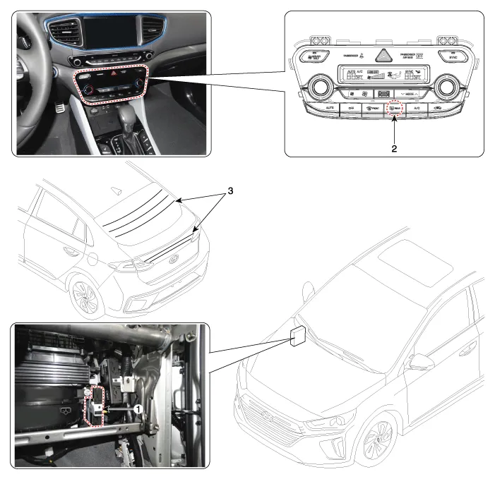
| 1. Body control module (BCM) 2. Rear glass defogger switch | 3. Rear glass defogger |
Inspection • Wrap tin foil around the end of the voltmeter test lead to prevent damaging the heater line. Apply finger pressure on the tin foil, moving the tin foil along the grid line to check for open circuits.
Other information:
Hyundai Ioniq (AE) 2017-2022 Service & Repair Manual: A/C Pressure Transducer. Description and operation
DescriptionThe A/C Pressure Transducer (APT) converts the pressure value of high pressure line into voltage value after measuring it. By converted voltage value, engine ECU controls the cooling fan by operating it high speed or low speed. Engine ECU stops the operation of the compressor when the temperature of refrigerant line is very high or very
Hyundai Ioniq (AE) 2017-2022 Service & Repair Manual: Troubleshooting
Trouble Symptom ChartsTrouble Symptom 1Trouble Symptom 2 Trouble symptom Probable cause Remedy The set vehicle speed varies greatly upward or downward"Surging" (repeated alternating acceleration and deceleration) occurs after settingMalfunction of the vehicle speed se
Categories
- Manuals Home
- Hyundai Ioniq Owners Manual
- Hyundai Ioniq Service Manual
- Hybrid Vehicle Engine Compartment
- Engine Control/Fuel System
- Checking the Coolant Level
- New on site
- Most important about car
