Hyundai Ioniq: Cylinder Head Assembly / Cylinder Head. Repair procedures
Engine removal is not required for this procedure.
| •
| Be sure to read and follow the "General Safety Information and Caution" before doing any work related with the high voltage system. Failure to follow the safety instructions may result in serious electrical injuries. |
| •
| Be sure to read and follow the "High Voltage Shut-off Procedures" before doing any work related with the high voltage system. Failure to follow the safety instructions may result in serious electrical injuries. |
|
| •
| Use fender covers to avoid damaging painted surfaces. |
| •
| To avoid damaging the cylinder head, wait until the engine coolant temperature drops below normal temperature (20°C [68°F]) before removing it. |
| •
| When handling a metal gasket, take care not to fold the gasket or damage the contact surface of the gasket. |
| •
| To avoid damage, unplug the wiring connectors carefully while holding the connector portion. |
|
| •
| Mark all wiring and hoses to avoid misconnection. |
| •
| Turn the crankshaft damper pulley so that the No.1 piston is at top dead center. |
|
| 1. | Shut off the High Voltage circuit. (Refer to General Information - "High Voltage Shutoff Procedure") |
| 2. | Disconnect the battery negative terminal. |
| 3. | Remove the air cleaner assembly. (Refer to Intake and Exhaust System - "Air Cleaner") |
| 4. | Remove the RH front wheel. (Refer to Suspension System - "Wheel") |
| 5. | Remove the engine room under cover. (Refer to Engine and Transaxle Assembly - "Engine Room Under Cover") |
| 6. | Loosen the drain plug, and drain the engine coolant. Remove the reservoir cap to help drain the coolant faster. (Refer to Cooling System - "Coolant") |
| 7. | Loosen the drain plug, and drain the inverter coolant. Remove the reservoir cap to help drain the coolant faster. (Refer to Hybrid Motor System - "Coolant") |
| 8. | Disconnect the electric water pump (EWP) coolant hose (A). 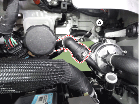
|
| 9. | Disconnect the fuel hose (A) and the purge control solenoid valve (PCSV) hose (B). 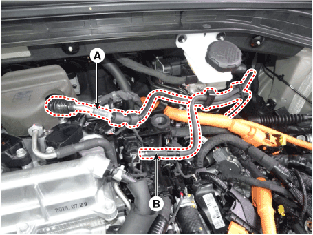
|
| 10. | Disconnect the wiring connectors and harness clamps and remove the connector brackets around the cylinder head. 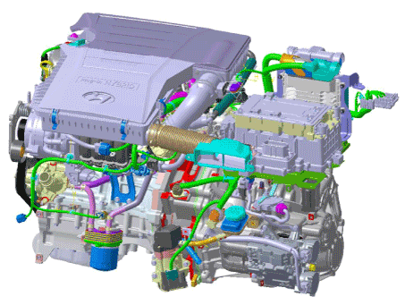
|
| 11. | Disconnect the heater hoses (A). 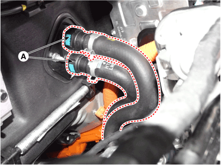
|
| 12. | Disconnect the radiator upper hose (A). 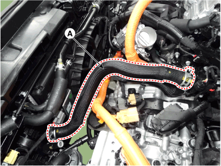
| •
| When installing radiator hoses, install as shown in illustrations. 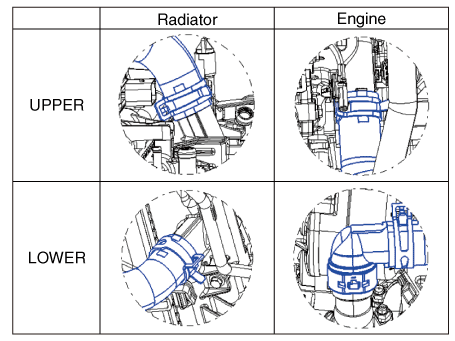
|
|
|
| 13. | Disconnect the radiator lower hose (A). 
| •
| When installing radiator hoses, install as shown in illustrations. 
|
|
| •
| When the radiator lower hose detached, remove the holder clip (A) and then disconnect the quick connector. 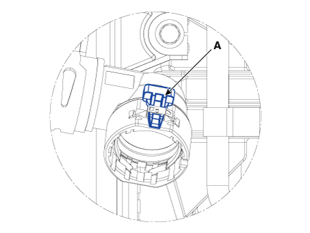
|
|
|
| 14. | Remove the water temperature control assembly. (Refer to Cooling System - "Water Temperature Control Assembly") |
| 15. | Remove the cylinder head cover. (Refer to Cylinder Head Assembly - "Cylinder Head Cover") |
| 16. | Remove the intake manifold. (Refer to Intake and Exhaust System - "Intake Manifold") |
| 17. | Remove the exhaust manifold. (Refer to Intake and Exhaust System - "Exhaust Manifold") |
| 18. | Remove the timing chain. (Refer to Timing System - "Timing Chain") |
| 19. | Remove the heater pipe. (Refer to Cooling System - "Water Temperature Control Assembly") |
| 20. | Remove the electric EGR (EEGR) control valve. (Refer to Engine Control / Fuel System - "Electric EGR Control Valve (EEGR)") |
| 21. | Remove the CVVT & camshaft. (Refer to Cylinder Head Assembly - "CVVT & Camshaft") |
| 22. | Remove the hydraulic lash adjuster (HLA) (A) and the swing arm (B). 
| •
| The HLA and swing arm should be kept together as pairs during storage after removal and reinstallation. |
|
|
| 23. | Remove the spark plugs. (Refer to Engine Electrical System - "Spark Plug") |
| 24. | Remove the cylinder head. | (1) | Using bit socket (12PT), uniformly loosen and remove the cylinder head bolts, in several passes, in the sequence as shown. 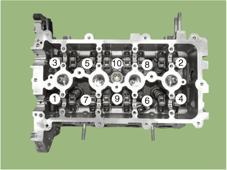
| •
| Head warpage or cracking could result from removing bolts in an incorrect order. |
|
|
| (2) | Lift the cylinder head (A) from the dowels on the cylinder block and place the cylinder head on wooden blocks on a bench. 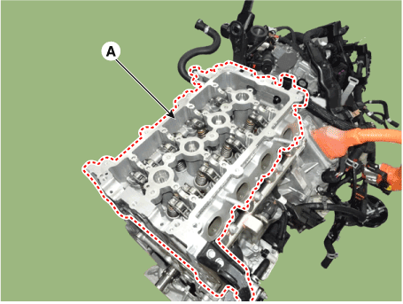
| •
| Be careful not to damage the contact surfaces of the cylinder head and cylinder block. |
|
|
| (3) | Remove the cylinder head gasket (B). 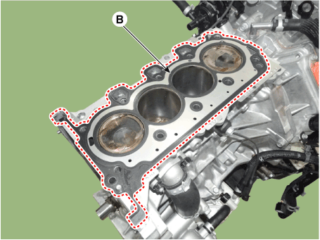
|
|
| •
| Identify, valves and valve springs as they are removed so that each item can be reinstalled in its original position. |
|
| 1. | Remove the valves. | (1) | Using the SST (09222-3K000, 09222-3K100), press the valve spring and remove the retainer lock (A). 
| •
| Do not press valve retainer more than 12mm (0.47 in.) |
| •
| When installing the SST, insert the front support directly into the bolt hole on the cylinder head. |
|
|
| (2) | Remove the spring retainer (B). |
| (3) | Remove the valve spring (C). |
| (5) | Using the pliers, remove the valve stem seal (D). 
| •
| Do not reuse old valve stem seals. |
|
|
|
Cylinder Head
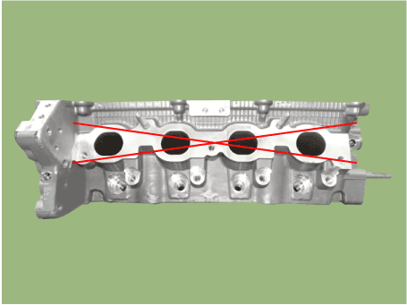
| 1. | Inspect for flatness. Using a precision straight edge and feeler gauge, measure the surface contacting cylinder block and the manifolds for warpage. Flatness of cylinder head gasket surface Standard : Less than 0.05 mm (0.0020 in) Less than 0.02 mm (0.0008 in) / 100x100 Flatness of manifold gasket surface Standard : Less than 0.1 mm (0.0039 in) |

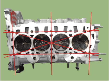
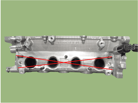
|
| 2. | Inspect for cracks. Check the combustion chamber, intake ports, exhaust ports and cylinder block surface for cracks. If cracked, replace the cylinder head. |
Valve and Valve Spring
| 1. | Inspect valve stems and valve guides. | (1) | Using a caliper gauge, measure the inside diameter of the valve guide. Valve guide I.D. Intake / Exhaust : 5.500 - 5.512 mm (0.2165 - 0.2170 in) |

|
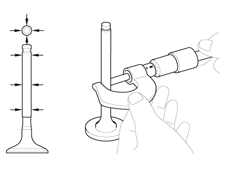
| (2) | Using a micrometer, measure the diameter of the valve stem. Valve stem O.D. Intake : 5.465 - 5.480 mm (0.2151 - 0.2157 in) Exhaust : 5.448 - 5.470 mm (0.2144 - 0.2154 in) |
|
| (3) | Subtract the valve stem diameter measurement from the valve guide inside diameter measurement. Valve stem-to-guide clearance Intake : 0.020 - 0.047 mm (0.00078 - 0.00185 in) Exhaust :0.030 - 0.064 mm (0.00118 - 0.00251 in) |
|
|
| 2. | Inspect valves. | (1) | Check the valve is ground to the correct valve face angle. Valve face angle : Intake/Exhaust : 45.25° - 45.75° |
|
| (2) | Check that the surface of the valve for wear. If the valve face is worn, replace the valve. |
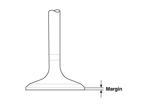
| (3) | Check the valve head margin thickness. If the margin thickness is less than minimum, replace the valve. Margin Intake : 1.35 - 1.65 mm (0.0531 - 0.0650 in) Exhaust : 1.60 - 1.90 mm (0.0630 - 0.0748 in) |
|
| (4) | Check the valve length. Length Intake : 100.94 mm (3.9740 in) Exhaust : 101.09 mm (3.9799 in) |
|
| (5) | Check the surface of the valve stem tip for wear. If the valve stem tip is worn, replace the valve. |
|
| 3. | Inspect valve seats. | (1) | Check the valve seat for evidence of overheating and improper contact with the valve face. If the valve seat is worn, replace cylinder head. |
| (2) | Before reconditioning the seat, check the valve guide for wear. If the valve guide is worn, replace cylinder head. |
| (3) | Recondition the valve seat with a valve seat grinder or cutter. The valve seat contact width should be within specifications and centered on the valve face. |
|
| 4. | Inspect valve springs. | (1) | Using a steel square, measure the out-of-square of the valve spring. |
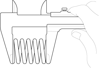
| (2) | Using vernier calipers, measure the free length of the valve spring. Valve spring Standard : Free height : 50.27 mm (1.9791 in) Load : 16.4 ± 0.8 kgf.m / 35.5 mm (161 ± 8 N / 1.3976 in.) 26.0 ± 0.9 kgf.m / 27.7 mm (255 ± 9 N / 1.0905 in.) Out of squareness : 1.5° MAX |
|
|
HLA (Hydraulic Lash Adjuster)
With the HLA filled with engine oil, hold A and press B by hand. If B moves, replace the HLA.

Problem
| Possible cause
| Action
|
1. Temporary noise when starting a cold engine
| Normal
| This noise will disappear after the oil in the engine reaches the normal pressure.
|
2. Continuous noise when the engine is started after parking more than 48 hours
| Oil leakage of the high pressure chamber on the HLA, allowing air to get in
| Noise will disappear within 15 minutes when engine runs at 2000-3000 rpm.
If it doesn’t disappear, refer to step 7 below.
|
3. Continuous noise when the engine is first started after rebuilding cylinder head
| Insufficient oil in cylinder head oil gallery
|
4. Continuous noise when the engine is started after excessively cranking the engine by the starter motor or band
| | •
| Oil leakage of the high-pressure chamber in the HLA, allowing air to get in |
| •
| Insufficient oil in the HLA |
|
5. Continuous noise when the engine is running after changing the HLA
| | •
| Do not run engine at a speed higher than 3000 rpm, as this may damage the HLA. |
|
|
6. Continuous noise during idle after high engine speed
| Engine oil level too high or too low
| | •
| Drain or add oil as necessary. |
|
Excessive amount of air in the oil at high engine speed
| Check oil supply system.
|
Deteriorated oil
| Check oil quality.
If deteriorated, replace with specified type.
|
7. Noise continues for more than 15 minutes
| Low oil pressure
| Check oil pressure and oil supply system of each part of engine.
|
Faulty HLA
| Remove the cylinder head cover and press HLA down by hand.
If it moves, replace the HLA.
|
| •
| Thoroughly clean all parts to be assembled. |
| •
| Before installing the parts, apply fresh engine oil to all sliding and rotating surfaces. |
|
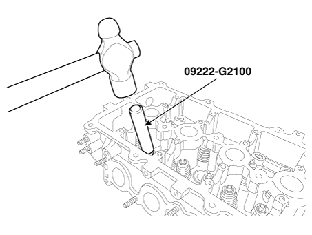
| 1. | Install the valves. | (1) | Using the SST (09222-G2100), push in a new valve stem seal. | •
| Do not reuse old valve stem seals. |
| •
| Incorrect installation of the seal could result in oil leakage past the valve guides. |
|
|
| (2) | Install the valve, valve spring and spring retainer. | •
| Place valve springs so that the cone shape side is upward retainer side. |
|
|
| (3) | Using the SST (09222-3K000, 09222-3K100), compress the spring and install the retainer locks. After installing the valves, ensure that the retainer locks are correctly in place before releasing the valve spring compressor. 
| •
| When installing the SST, insert the front support directly into the bolt hole on the cylinder head. |
|
| •
| Do not press valve retainer more than 12 mm (0.47 in.). |
|
|
| (4) | Lightly tap the end of each valve stem two or three times with the wooden handle of a hammer to ensure proper seating of the valve and retainer lock. |
|
| •
| Thoroughly clean all parts to be assembled. |
| •
| Always use new cylinder head and manifold gaskets. |
| •
| Always use new cylinder head bolts. Cylinder head bolts are toque-to-yield bolts designed to be permanently elongated beyond the state of elasticity when torqued, so if the bolts are removed and reused, it may cause the bolts to break or fail to maintain clamping force. |
| •
| The cylinder head gasket is a metal gasket. Take care not to bend it. |
| •
| Rotate the crankshaft to set the No.1 piston at TDC (Top dead center) on compression stroke. |
|
| 1. | Install the cylinder head gasket. | (1) | The sealant locations on cylinder head gasket, cylinder block and cylinder head must be free of engine oil and etc. |
| (2) | Apply sealant on the cylinder block top surface (Refer to below illustration) before assembling the cylinder head gasket. 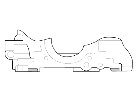
|
| (3) | Install the cylinder head gasket (B) on the cylinder block. 
| •
| Be careful of the installation direction. |
|
|
| (4) | Install the cylinder head gasket with the dowel pins of the cylinder block. |
| (5) | Apply sealant on the cylinder head gasket top surface (Refer to below illustration) after assembling the cylinder head gasket. 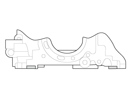
| •
| Assemble the cylinder head gasket and the cylinder head within 5 minutes after applying sealant. |
|
|
|
| 2. | Place the cylinder head (A) carefully to protect damage to the head gasket during installation. 
|
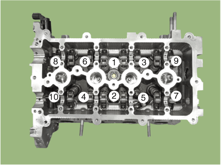
| 3. | Install the cylinder head bolts with washers. Using SST (09221-4A000), install and tighten the 10 cylinder head bolts, in several passes, in the sequence as shown. Tightening torque P/N : 22320-03000 1st step : 14.7 N.m (1.5 kgf.m, 10.8 lb-ft) 2nd step : 90° 3rd step : 120° P/N : 22320-03HA0 1st step : 14.7 N.m (1.5 kgf.m, 10.8 lb-ft) 2nd step : 120° 3rd step : 120° |

| •
| Do not reuse the cylinder head bolts. |
| •
| Do not apply engine oil on the bolt threads to achieve correct torque. |
| •
| Remove the extruded sealant within 5 minutes after installing cylinder head bolts. |
| •
| The engine running or pressure test should not be performed within 30 minutes after installing cylinder head bolts. |
| •
| Be careful not to change the installing position of the preassembled washer bolts and non-preassembled washer bolts. |
| •
| When installing the washer of the non-preassembled washer bolts, the round and chamfer of washers should be faced up. |

|
|
| 4. | Install the spark plugs. (Refer to Engine Electrical System - "Spark Plug") |
| 5. | Install the hydraulic lash adjuster (HLA) (A) and the swing arm (B). 
| (1) | When installing HLA, it should be held upright so that engine oil in HLA may not spill and assured that dust does not adhere to HLA. |
| (2) | HLA should be inserted carefully to the cylinder head not to spill engine oil. If engine oil has spilled out of the lash adjuster, HLA bleeding should be performed according to the below procedure. | •
| Stroke the lash adjuster in engine oil by pushing its cap 4 to 5 times while pushing the ball down slightly using a hard steel wire. Be careful not to give the ball a hard push because the ball weighs just several grams. If installing with engine oil spilling out of the lash adjuster and air in it, it might make an abnormal noise. 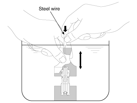
|
|
|
|
| 6. | Install the other parts reverse order of removal. |
| 7. | Connect the High Voltage circuit. (Refer to General Information - "High Voltage Shutoff Procedure") | •
| Refill engine with engine oil. |
| •
| Refill an engine radiator and a reservoir tank with coolant. |
| •
| Refill an inverter radiator and a reservoir tank with coolant. |
| •
| Clean battery posts and cable terminals and assemble. |
| •
| Inspect for fuel leakage. |
| –
| After assemble the fuel line, turn on the ignition switch (do not operate the starter) so that the fuel pump runs for approximately two seconds and fuel line pressurizes. |
| –
| Repeat this operation two or three times, then check for fuel leakage at any point in the fuel line. |
| •
| Bleed air from the hybrid motor cooling system. (Refer to Hybrid Motor System - "Coolant") |
| •
| Bleed air from the engine cooling system. |
| –
| Start engine and let it run until it warms up. (until the radiator fan operates 3 or 4 times.) |
| –
| Turn Off the engine. Check the level in the radiator, add coolant if needed. This will allow trapped air to be removed from the cooling system. |
| –
| Put radiator cap on tightly, then run the engine again and check for leaks. |
|
|
Other information:
Replacement[LH]
•
Put on gloves to prevent hand injuries.
•
When removing with a flat-tip screwdriver or remover, wrap protective tape around the tools to prevent damage to components...
1. Steering wheel audio controls/Bluetooth® wireless technology hands-free controls
2. Instrument cluster
3. Horn
4. Driver’s front air bag
5. Cruise controls/Smart cruise controls
6. Engine Start/Stop button
7. Light control/Turn signals
8. Wiper/Washer
9...
Categories
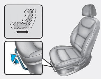
The front seat can be adjusted by using the levers located on the outside of
the seat cushion. Before driving, adjust the seat to the proper position so that
you can easily control the steering wheel, foot pedals and controls on the instrument
panel.
Forward and rearward adjustment
read more


