
Hyundai Ioniq (AE): Seat Electrical / Seat Heater. Components and components location
| Component Location |
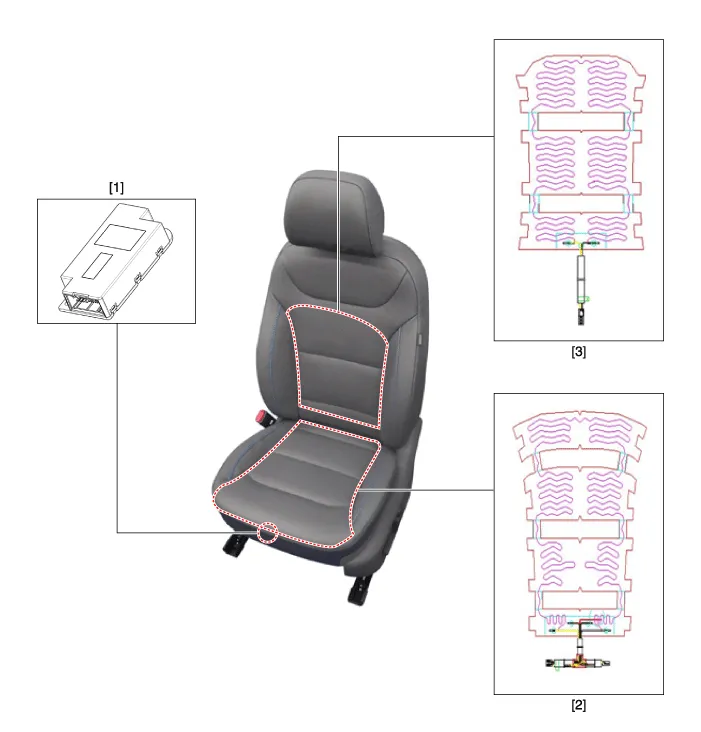
| 1. Seat heater unit (Passenger seat only) 2. Seat chusion heater | 3. Seat back (Heater) |
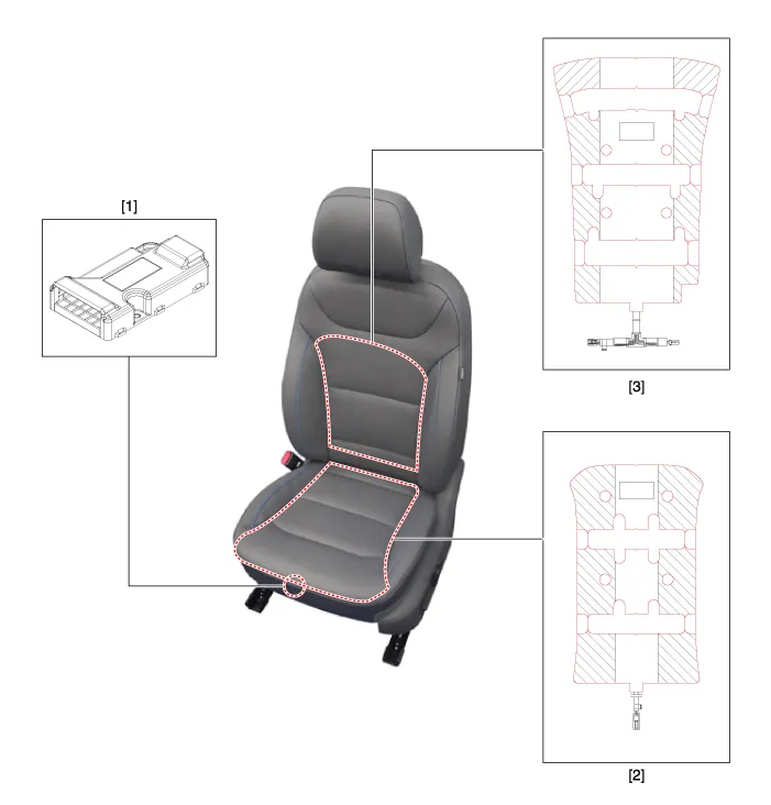
| 1. Air ventilation unit (Passenger seat only) 2. Seat cushion (Heater) | 3. Seat back (Heater) |
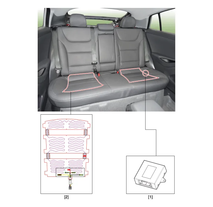
| 1. Rear seat heater unit (Passenger seat only) | 2. Seat cushion (Heater) |
InspectionSeat Control Switch1.With the power seat switch in each position, make sure that continuity exists between the terminals below. If continuity is not as specified, replace the power seat switch.
Circuit Diagram[Front Seat Heater (Non-Air Ventilation)][Rear Seat Heater (Bench Type)]
Other information:
Hyundai Ioniq (AE) 2017-2022 Service & Repair Manual: Ambient Temperature Sensor. Repair procedures
Inspection1.Check the resistance of the ambient temperature sensor between terminals 1 and 2 whether it changes by changing the ambient temperature.1. Ambient Sensor (+)2. Sensor groundSpecification Ambient temperature [°C (°F)] Resistance between terminal 1 and 2 (
Hyundai Ioniq (AE) 2017-2022 Service & Repair Manual: Auto Defoging Actuator. Description and operation
DescriptionThe auto defogging sensor is installed on front window glass. The sensor judges and sends signal if moisture occurs to blow out wind for defogging. The air conditioner control module receives a signal from the sensor and restrains moisture and eliminates defog by the intake actuator, A/C, auto defogging actuator, blower motor rpm and mod
Categories
- Manuals Home
- Hyundai Ioniq Owners Manual
- Hyundai Ioniq Service Manual
- Components and components location
- Transmission Gear Oil. Repair procedures
- Front Disc Brake. Repair procedures
- New on site
- Most important about car
