Hyundai Ioniq: Controller. Heater & A/C Control Unit (DATC) / Components and components location
Hyundai Ioniq (AE) 2017-2025 Service Manual / Heating, Ventilation and Air Conditioning / Controller. Heater & A/C Control Unit (DATC) / Components and components location
| Components |
| Connector Pin Function |
[Connector A]
|
Pin NO
|
Funtion
|
Pin NO
|
Funtion
|
| 1 | Battery (+) | 21 | IGN1 |
| 2 | - | 22 | IGN2 |
| 3 | ILL+ (TAIL) | 23 | Blower PWM |
| 4 | Sensor REF (+5V) | 24 | Left Photo Sensor (-) |
| 5 | Driver Mode Control Actuator Feedback | 25 | Right Photo Sensor (-) |
| 6 | Driver Temperature Control Actuator Feedback | 26 | Blower Relay |
| 7 | Intake Actuator Feedback | 27 | Incar sensor (+) |
| 8 | Evaporator Temperature Sensor (+) | 28 | Incar motor (-) |
| 9 | Ambient Temperature Sensor (+) | 29 | - |
| 10 | Dirver Mode Control Actuator (VENT) | 30 | Detent out (-) |
| 11 | Dirver Mode Control Actuator (DEF) | 31 | - |
| 12 | Driver Temperature Control Actuator (COOL) | 32 | - |
| 13 | Driver Temperature Control Actuator (WARM) | 33 | P CAN HIGH |
| 14 | Intake Actuator (FRE) | 34 | P CAN LOW |
| 15 | Intake Actuator (REC) | 35 | Climate_CAN High |
| 16 | Passenger Temperature Control Actuator (COOL) | 36 | Climate_CAN Low |
| 17 | Passenger Temperature Control Actuator (WARM) | 37 | Interlock (+)_Ecomp |
| 18 | HTD (Rear Defrost) | 38 | Interlock (-)_Ecomp |
| 19 | Reae defogging switch | 39 | Sensor Ground |
| 20 | ILL - (RHEO) | 40 | Ground |
[Connector B]
|
Pin NO
|
Funtion
|
Pin NO
|
Funtion
|
| 1 | PTC Relay 1 | 17 | PAB Off Signal |
| 2 | PTC Relay 2 | 18 | Passenger Mode Control Actuator (Vent) |
| 3 | - | 19 | Passenger Mode Control Actuator (Defrost) |
| 4 | - | 20 | Passenger Mode Control Actuator Feedback |
| 5 | Auto Defogging Actuator (OPEN) | 21 | Duct Sensor (+)_Vent |
| 6 | Auto Defogging Actuator (CLOSE) | 22 | Duct Sensor (+)_Floor |
| 7 | - | 23 | - |
| 8 | - | 24 | - |
| 9 | - | 25 | Passenger Temperature Control Actuator Feedback |
| 10 | - | 26 | - |
| 11 | PAB IGN 1 | 27 | - |
| 12 | ADS Signal | 28 | Auto Defogging Actuator Feedback |
| 13 | - | 29 | - |
| 14 | - | 30 | - |
| 15 | PAB On Signal | 31 | - |
| 16 | Ground | 32 | - |

 Repair procedures
Self Diagnosis1.Self-diagnosis process.
•
When operating the self-diagnostics, the below fault (self-diagnostics code) will blink at 0...
Other information:
Hyundai Ioniq (AE) 2017-2025 Service Manual: Air Ventilation Seat. Repair procedures
Removal[Ventilation Blower]1.Disconnect the negative (-) battery terminal.2.Remove the front seat.(Refer to Body - "Front Seat Assembly") 3.Remove the blower duct.4.Remove the blower FAN (A) after removing the screws.[Ventilation Seat Unit]1.Disconnect the negative (-) battery terminal...
Hyundai Ioniq (AE) 2017-2025 Service Manual: Lumber Support Units. Repair procedures
Removal1.Disconnect the negative (-) battery terminal.2.Remove the front seat assembly.(Refer to Body - "Front Seat Assembly")3.Remove the seat back.(Refer to Body - "Front Seat Back Cover")4.Disconnect the lumber support motor connector (A).5.Separate the retaining clips (A) from the seat frame...
Categories
- Manuals Home
- 1st Generation Ioniq Owners Manual
- 1st Generation Ioniq Service Manual
- Check Hybrid system, Check Hybrid system. Turn engine Off
- How to Disconnect Normal Charger
- Tilt Steering / Telescope Steering
- New on site
- Most important about car
Seatback pocket
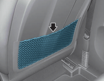
The seatback pocket is provided on the back of the front passenger's seatback.
WARNING
To prevent the Occupant Classification System from malfunctioning:

Copyright © 2025 www.hioniqae.com