Hyundai Ioniq (AE): Cylinder Head Assembly / CVVT & Camshaft. Components and components location
| Components |
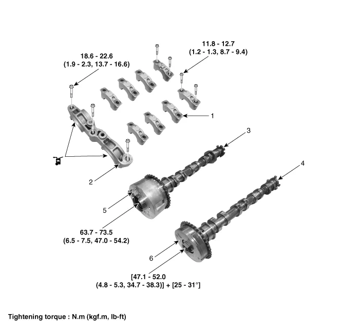
| 1. Camshaft bearing cap 2. Front camshaft bearing cap 3. Exhaust camshaft | 4. Intake camshaft 5. Exhaust CVVT assembly 6. Intake CVVT assembly |
Removal • Use fender covers to avoid damaging painted surfaces. • To avoid damage, unplug the wiring connectors carefully while holding the connector portion.
DescriptionThe continuous variable valve timing (CVVT) system advances or retards the opening of an intake or exhaust valve according to the ECM signals that are determined based on engine RPM and load.
Other information:
Hyundai Ioniq (AE) 2017-2022 Service & Repair Manual: Heater Core. Repair procedures
Replacement1.Disconnect the negative (-) battery terminal. 2.Remove the heater and blower assembly.(Refer to Heater - "Heater Unit") 3.Loosen the mounting screws and remove the driver's temperature control actuator (A).4.Remove the heater core cover (A) after loosening the mounting screws.
Hyundai Ioniq (AE) 2017-2022 Service & Repair Manual: Rear Corner Safety ON/OFF Switch. Repair procedures
Inspection1.Disconnect the negative (-) battery terminal.2.Remove the crash pad lower panel.(Refer to Body - "Crash Pad Lower Panel")3.Remove the lower crash pad switch assembly (A) after disengaging the mounting clip.4.Remove the rheostat switch connector (A).
Categories
- Manuals Home
- Hyundai Ioniq Owners Manual
- Hyundai Ioniq Service Manual
- Transmission Gear Oil. Repair procedures
- Body (Interior and Exterior)
- Front Disc Brake. Repair procedures
- New on site
- Most important about car
