Hyundai Ioniq: Indicators And Gauges / Instrument Cluster. Description and operation
Hyundai Ioniq (AE) 2017-2025 Service Manual / Body Electrical System / Indicators And Gauges / Instrument Cluster. Description and operation
| Description |
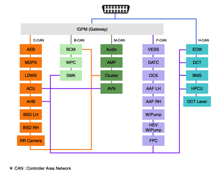
Communication Network Diagram
| Abbreviation | Expalnation |
| AAF | Active Air Flap |
| ACU | Airbag Control Unit |
| AEB | Autonomous Emergency Braking |
| AHB | Active Hybrid Brake System |
| AMP | Amplifier |
| AVN | Head Unit (Audio / AVN) |
| B_CAN | Body Controller Area Network |
| BCM | Body Control Module |
| BMS | Battery Management System |
| BSD | Blind Spot Detection |
| C_CAN | Chassis Controller Area Network |
| CARMERA | Rear View Carmera |
| CLU | Cluster Module |
| DATC | Dual Automatic Temp Control |
| FPCM | Fuel Pump Control Module |
| HPCU | Hybrid Power Unit |
| IGPM | Intergrated Gateway & Power control Module |
| LDWS | Lane Departure Warning System |
| M_CAN | Multi media Controller Area Network |
| MDPS | Motor Driven Power Steering |
| P_CAN | Powertrain Controller Area Network |
| PAS | Parking Assist System |
| SJB | Smart Junction Block |
| SMK | Smart Key Unit |
| TCM(DCT) | Double Clutch Transmission Unit |
| VESS | Virtual Engine Sound System |
Cluster Variant Coding
As we have more options (ESC, MDPS, SCC, etc.) in the car, the dashboard now have more information to display depending on the chosen options.
For this reason, we need to learn which options the current vehicle when we replace the dashboard.
To address this issue, a course of learning based on the option required for the vehicle when replacing the dashboard should be carried out.
This is called Variant Coding.
Function
| 1. | High speed CAN communication (C-CAN)
|
| 2. | Low speed CAN communication (MM-CAN)
|
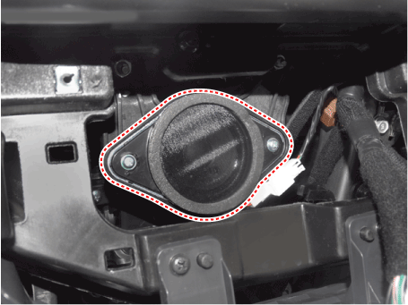
| 3. | Sound output Instrument cluster and the external speakers connected to the output of the various beeps and sound effects. If External AMP is applied, the directional alarm is outputted through the amp.
|
| 4. | User Setting Mode (USM) Setting can be changed by using switchs (Menu, UP, Down and OK button). There are many items (for example, In/Out Seat Synchronization, In/Out Steering Wheel Synchronization, Auto Door Lock, Auto Door Lock Deactivate, Head Lamp Escort, Welcome Light, Welcome Sound, One Touch Turn Signal, Average Fuel Consumption Auto Reset, Brightness, and Content Setup) that can be set and customized. The signal flow during setting is as follows.
|
Hybrid Mian Features
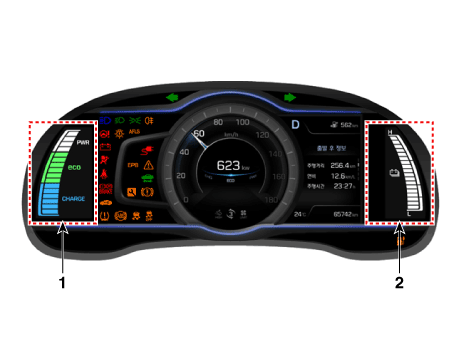
| 1. | ECO and power guage
|
| 2. | SOC(State of Charge) guage
|
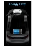
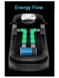
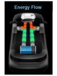
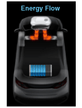
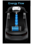
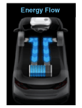
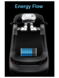
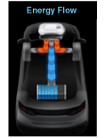
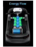
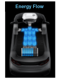
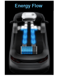
| 3. | Energy Flow
|
Other information:
Hyundai Ioniq (AE) 2017-2025 Service Manual: Front Seat Assembly. Repair procedures
Replacement1.Open the cover and loosen the front seat mounting bolts. [Front] Tightening torque : 49.0 - 58.8 N.m (5.0 - 6.0 kgf.m, 36.2 - 43.4 lb-ft) [Rear] 2.Disconnect the main connector (A), front seat belt buckle connector (C), airbag connector (B)...
Hyundai Ioniq (AE) 2017-2025 Service Manual: Clutch Cover And Disc. Components and components location
C..
Categories
- Manuals Home
- 1st Generation Ioniq Owners Manual
- 1st Generation Ioniq Service Manual
- High Beam Assist (HBA)
- Reverse Parking Aid Function
- Towing
- New on site
- Most important about car
Driver Position Memory System
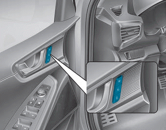
The Driver Position Memory System is provided to store and recall the following memory settings with a simple button operation.
- Driver's seat position
- Side view mirror position
- Instrument panel illumination intensity
Copyright © 2025 www.hioniqae.com

