Hyundai Ioniq: Brake System / Rear Disc Brake. Repair procedures
Hyundai Ioniq (AE) 2017-2025 Service Manual / Brake System / Brake System / Rear Disc Brake. Repair procedures
| Removal |
[EPB None Apply]
| 1. | Loosen the wheel nuts slightly. Raise the vehicle, and make sure it is securely supported. |
| 2. | Remove the rear wheel and tire (A) from the rear hub.
|
| 3. | Remove the parking brake cable fixed clip (A).
|
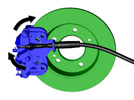
| 4. | Pull the operating lever as a direction of arrow in the illustration below and then remove the parking brake cable.
|
| 5. | Loosen the guide rod bolt and then pivot the caliper body up out of the way.
|
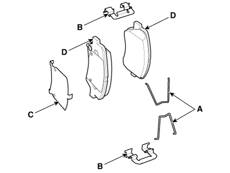
| 6. | Remove the pad return spring (A).
|
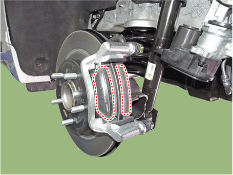
| 7. | Separate the brake pad and pad retainer.
|
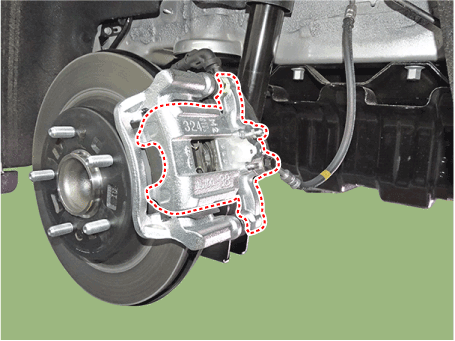
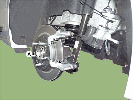
| 8. | Loosen the caliper mounting bolts and then removethe rear caliper assembly (A).
|
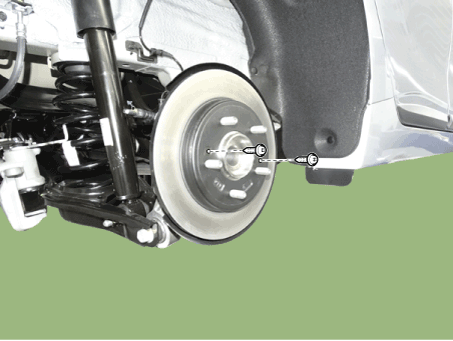
| 9. | Remove the rear brake disc by loosening the screws.
|
[EPB Apply]
| 1. | Loosen the wheel nuts slightly. Raise the vehicle, and make sure it is securely supported. |
| 2. | Remove the rear wheel and tire (A) from the rear hub.
|
| 3. | Disconnect the EPB connector.
|
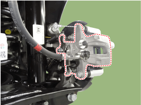
| 4. | Loosen the guide rod bolt and then remove the caliper body.
|
| 5. | Remove the pad return spring (A).
|
| 6. | Remove the brake pad.
|
| 7. | Remove the pad retainer (A).
|
| 8. | Loosen the caliper mounting bolts and then removethe rear caliper assembly (A).
|
| 9. | Remove the rear brake disc by loosening the screws.
|
| Replacement |
Brake Pad
| [EPB None Apply] |
| 1. | Loosen the wheel nuts slightly. Raise the vehicle, and make sure it is securely supported. |
| 2. | Remove the rear wheel and tire (A) from the rear hub.
|
| 3. | Remove the parking brake cable fixed clip (A).
|
| 4. | Pull the operating lever as a direction of arrow in the illustration below and then remove the parking brake cable.
|
| 5. | Loosen the guide rod bolt and then pivot the caliper body up out of the way.
|
| 6. | Remove the pad return spring (A).
|
| 7. | Replace the brake pad and pad retainer.
|
| 8. | Install the pad return spring (A).
|
| 9. | Use a SST (09580-0U000) when installing the brake caliper assembly.
|
| 10. | Install the caliper body (A) then tighten the guide rod bolt (B).
|
| 11. | Pull the operating lever as a direction of arrow in the illustration below and then install the parking brake cable.
|
| 12. | Install the parking brake cable fixed clip (A).
|
| 13. | Install the rear wheel and tire (A) from the rear hub.
|
| [EPB Apply] |
| 1. | Loosen the wheel nuts slightly. Raise the vehicle, and make sure it is securely supported. |
| 2. | Remove the rear wheel and tire (A) from the rear hub.
|
| 3. | Disconnect the EPB connector.
|
| 4. | Loosen the guide rod bolt and then remove the caliper body.
|
| 5. | Remove the pad return spring (A).
|
| 6. | Remove the brake pad.
|
| 7. | Remove the pad retainer (A).
|
| 8. | Install the pad return spring (A).
|
| 9. | Install the caliper body (A) then tighten the guide rod bolt (B).
|
| 10. | Connect the EPB connector.
|
| 11. | Install the rear wheel and tire (A) from the rear hub.
|
| Inspection |
Rear Brake Disc Thickness Check
| 1. | Check the brake pads for wear and fade. |
| 2. | Check the brake disc for damage and cracks. |
| 3. | Remove all rust and contamination from the surface, and measure the disc thickness at 24 points, at least, of same distance (5mm) from the brake disc outer circle.
|
| 4. | If wear exceeds the limit, replace the discs and pad assembly left and right of the vehicle. |
Rear Brake Pad Check
| 1. | Check the pad wear. Measure the pad thickness and replace it, if it is less than the specified value.
|
| 2. | Check the damage of pad, backing metal and contamination with grease. |
Rear Brake Disc Runout Check
| 1. | Place a dial gauge about 10mm (0.2 in.) from the outer circumference of the brake disc, and measure the runout of the disc.
|
| 2. | If the runout of the brake disc exceeds the limit specification, replace the disc, and then measure the runout again. |
| 3. | If the runout exceeds the limit specification, install the brake disc after turning it 180° and then check the runout of the brake disc again. |
| 4. | If the runout cannot be corrected by changing the position of the brake disc, replace the brake disc. |
| Installation |
| 1. | To install, reverse the removal procedure. |
| 2. | Use a SST (09580-0U000) when installing the brake caliper assembly.
|
| 3. | After installing, bleed the brake system. (Refer to Brake System - "Brake System Bleeding") |
| Adjustment |
Parking Brake
|
| 1. | Remove the floor console to reach the adjusting nut. |
| 2. | Loosen the parking brake cable until both operating levers rest in fully off position. |
| 3. | Bring the brake pads in their operating position by pressing the brake pedal down several times until there is resistance. |
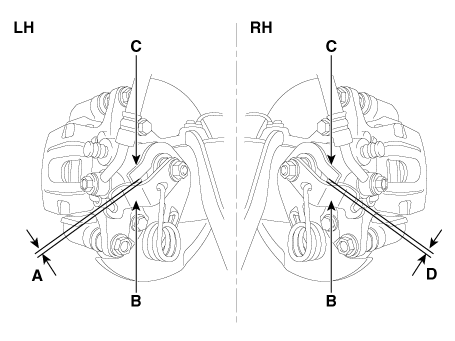
| 4. | Tension the parking brake cable by tightening the adjusting nut, until the operating levers on both calipers lift from the stop, up to a distance of (A) and (D) between operating lever (B) and stopper (C).
|
| 5. | Refit the floor console. |
| 6. | Parking brake lever in the car must be in fully loosened position. |
| 7. | If the handbrake cables where changed, actuate the parking brake a few times with maximum force to stretch the parking brake cables, and then control adjusting as above. |
| 8. | Check the wheels of their free operation. |
| 9. | Test drive. |
 Rear Disc Brake. Components and components location
Components[EPB None Apply]1. Brake pad2. Pad return spring3. Caliper carrier4. Pad retainer5. Caliper body6. Bleed screw7. Stopper8. Return spring9. Operating lever[EPB Apply]1...
Other information:
Hyundai Ioniq (AE) 2017-2025 Owner's Manual: Operating Door Locks from Outside the Vehicle
Mechanical key To remove the cover: 1. Pull out the door handle (1). 2. Press the lock (2) located inside the bottom part of the cover with a key or flat-head screwdriver. 3. Push out the cover while pressing the lock. To install the cover: 1. Pull out the door handle...
Hyundai Ioniq (AE) 2017-2025 Service Manual: Electric Parking Brake (EPB). Components and components location
C..
Categories
- Manuals Home
- 1st Generation Ioniq Owners Manual
- 1st Generation Ioniq Service Manual
- Folding the side view mirrors
- Check brakes/Check regenerative brakes, Check Virtual Engine Sound System
- Hybrid battery SOC (State of Charge) gauge
- New on site
- Most important about car
Rear Seats
Folding the rear seat
The rear seatbacks can be folded to facilitate carrying long items or to increase the luggage capacity of the vehicle.
WARNING
Never allow passengers to sit on top of the folded down seatback while the vehicle is moving. This is not a proper seating position and no seat belts are available for use. This could result in serious injury or death in case of an accident or sudden stop. Objects carried on the folded down seatback should not extend higher than the top of the front seatbacks. This could allow cargo to slide forward and cause injury or damage during sudden stops.
Copyright © 2025 www.hioniqae.com


