Hyundai Ioniq (AE): Fuses And Relays / Relay Box (Passenger Compartment). Components and components location
| Component Location |
| IGPM |
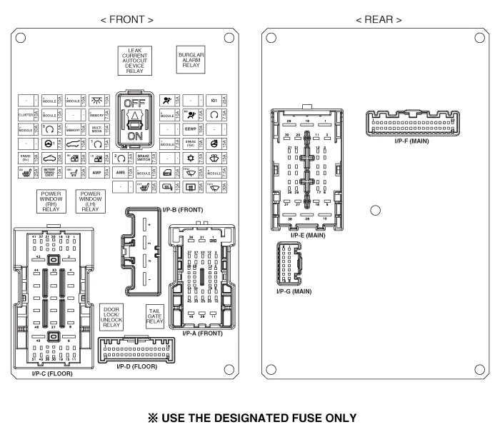
| Circuit (IGPM) |
Inspection1.Disconnect the negative (-) battery terminal.2.Pull out the relay from the engine compartment relay block.Power Relay (Type A) Check for continuity between the terminals.
DescriptionAuto Cut System of Dark Current Abbreviation Expalnation AAFActive Air FlapACUAirbag Control UnitAEBAutonomous Emergency BrakingAHBActive Hybrid Brake SystemAMPAmplifierAVNHead Unit (Audio / AVN)B_CANBody Controller Area NetworkBCMBody Control ModuleBMSBattery Management SystemBSDBlind Spot DetectionC_CANChassis Controller Area NetworkCARMERARear View CarmeraCLUCluster ModuleDATCDual Automatic Temp ControlFPCMFuel Pump Control ModuleHPCUHybrid Power UnitIGPMIntergrated Gateway & Power control ModuleLDWSLane Departure Warning SystemM_CANMulti media Controller Area NetworkMDPSMotor Driven Power SteeringP_CANPowertrain Controller Area NetworkPASParking Assist SystemSJBSmart Junction BlockSMKSmart Key UnitTCM(DCT)Double Clutch Transmission UnitVESSVirtual Engine Sound SystemSmart Junction Block (SJB) General function : Interior Junction Block + some functions of BCMIt controls loads with CAN communication and IPS.
Other information:
Hyundai Ioniq (AE) 2017-2022 Service & Repair Manual: Ambient Temperature Sensor. Components and components location
C
Hyundai Ioniq (AE) 2017-2022 Service & Repair Manual: Special service tools
Special Service Tools Tool Name / Number Illustration Description LKA Compensator(09964-C1100)Used for compensating front view camera unitBCW Sensor Correction Tool Set(09958-3T500)Used to correct the blind-spot radar unit.
Categories
- Manuals Home
- Hyundai Ioniq Owners Manual
- Hyundai Ioniq Service Manual
- Repair procedures
- Heating, Ventilation and Air Conditioning
- General Information
- New on site
- Most important about car
