Hyundai Ioniq: Fuses And Relays / Relay Box (Passenger Compartment). Description and operation
Auto Cut System of Dark Current
Abbreviation
| Expalnation
|
AAF
| Active Air Flap
|
ACU
| Airbag Control Unit
|
AEB
| Autonomous Emergency Braking
|
AHB
| Active Hybrid Brake System
|
AMP
| Amplifier
|
AVN
| Head Unit (Audio / AVN)
|
B_CAN
| Body Controller Area Network
|
BCM
| Body Control Module
|
BMS
| Battery Management System
|
BSD
| Blind Spot Detection
|
C_CAN
| Chassis Controller Area Network
|
CARMERA
| Rear View Carmera
|
CLU
| Cluster Module
|
DATC
| Dual Automatic Temp Control
|
FPCM
| Fuel Pump Control Module
|
HPCU
| Hybrid Power Unit
|
IGPM
| Intergrated Gateway & Power control Module
|
LDWS
| Lane Departure Warning System
|
M_CAN
| Multi media Controller Area Network
|
MDPS
| Motor Driven Power Steering
|
P_CAN
| Powertrain Controller Area Network
|
PAS
| Parking Assist System
|
SJB
| Smart Junction Block
|
SMK
| Smart Key Unit
|
TCM(DCT)
| Double Clutch Transmission Unit
|
VESS
| Virtual Engine Sound System
|
Smart Junction Block (SJB)
General function : Interior Junction Block + some functions of BCM
It controls loads with CAN communication and IPS.
IPS stands for Intelligent Power Switch, which uses the semiconductor technology to replace the current role of fuse and relay. (The IPS device protects the current load control function from the overcurrent.)
The advantages of IPS are as follows: | •
| Reduce relay and consequently decrease weight and volume |
| •
| Remove the relay operation noise |
| •
| Not necessary to replace fuse, increasing the product life |
|
SJB control entry
| 1. | Switch signal input | (1) | Assist seat belt switch Assist the door switch Driver's seat belt switch Rear left door switch Rear right door switch IGN1 switch IGN2 switch Brake fluid sensor Tailgate lid handle switch HID head lamp option Hazard lamp switch Head lamp low beams switch Hood switch Left front / rear turn signal switch Right front / rear turn signal switch Parking brake switch Driver the door lock/unlock control status Assist the door lock/unlock control status Rear left the door lock/unlock status Rear right the door lock/unlock status Driver the door switch Driver the door key lock switch Driver the door key unlock switch Driver the door power window lock switch Driver the door power window unlock switch |
| (2) | IPS&ARISU Left Head lamp low beams Right Head lamp low beams Left Head lamp high beams Right Head lamp high beams Room lamp Exterior left tail lamp Exterior right tail lamp Left front / rear turn signals Right front / rear turn signals DRL left lamp DRL right lamp Body resistance cut control Front left turn signal output Front right turn signal output |
| (3) | Relay Control Rear glass heater relay Tailgate lid relay Front glass heater relay Head lamp high beams relay Memory fuse switch relay Door lock/unlock relay Power window wake-up relay 2 Turn door lock relay |
|
| 2. | SJB protection | (1) | PCL (Programmable Current Limit) functions | –
| Replace the current junction box fuse function to protect the wire. |
| –
| How to operate : If the lamp current exceeds the standard level, cut off the lamp current to protect lamp. |
| –
| Lamp cut off time : 300ms or less. |
| –
| Applied load : Applied to all lamp loads controlled by SJB. |
| –
| Output the error code according to the error detection conditions. |
|
| (2) | OCL (Open Current Limit) | –
| Detect the lamp open state and inform the user of it. |
| –
| How to operate: Detect the current of the lamp and if it is below the standard level, change the lamp operation. |
| –
| Applied load: Applied to the turn signal lamp 4 channel |
| –
| Output the error code according to the error detection conditions. |
|
|
| 3. | SJB fail safe function | (1) | When SJB has a failed MCU (not operating due to a physical or electrical shock from the outside), the head lamp low and exterior and interior tail lamp are turned on to secure the driver if IGN2 is on and the head lamp low switch is on. |
| (2) | When the data transmission/reception fails due to a failed CAN communication line connected with SJB module (disconnection of both high and low line, high/low BAT short, high/low GND short), the head lamp low and interior/exterior tail lamps are turned on if IGN2 is on and the head lamp low switch is on. |
|
| 4. | Auto Cut System of Dark Current | (1) | Description : It cuts automatically power to be provided with load for reducing useless dark current according to vehicle state. 
|
| (2) | SJB had 3 modes, "Normal Mode", "Sleep Mode", "Power Off Mode". Auto cut of dark current practice in "Sleep Mode". | –
| "Sleep" condition : IG OFF, constant input switch, CAN network doesn't activate. |
| –
| "Sleep" resolutive condition : Any switch inputs, CAN network activates, KEY ON, IGN ON |
| –
| "Power OFF" condition : The setting time of timer which is used by cutting a load power expires. |
| –
| "Normal Mode" : SJB function normally activates. |
| –
| "Sleep Mode" : It is low power mode and activates for reducing electricity consumption of SJB or IPM. Auto cut of dark current function activates. |
| –
| "Power OFF Mode" : Power of MCU and circumferential circuit is cut for minimizing electricity consumption. Operation stops. |
|
| (3) | The explanation - The auto cut of dark current 
Before delivering to customer
| Fuse switch OFF
| | •
| All door close & RKE door lock or Constant switch state (Auto cut of dark current scenario starts.) |
| –
| After "sleep" state is for 5 min. |
| –
| SJB power down(SJB dark current : 200 μA) and cutting power of Lamp /Multimedia Load/Wake up/Immobilzer |
| 
|
After delivering to customer
| Fuse switch ON
| | •
| All door close & Constant switch state : C_BAState=OFF (Auto cut of dark current scenario starts.) |
| –
| After "sleep" state is for 20 min. |
| •
| In case RKE door lock : C_BAState=ON & Tailgate SW=CLOSE (Auto cut of dark current scenario starts.) |
| –
| After "Sleep" state 35s to 65s (Waiting time of other unit : 30 to 60s + SJB sleep counts 5s) |
| 
|
|
| (4) | Problem when fuse switch setting is wrong : If a fuse switch is set to OFF(Before delivering to customer) by a customer or technician and auto cut function of dark current activates, below problems may happen.
Symptom
| Related part
| | •
| Door lock/unlock, Tailgate open don't activate by RKE. (Wakeup of each module don't activate.) |
| BCM
| | •
| Digital clock is reset.(Memory is reset.) |
| Digital clock
| | •
| Setting value of audio(Volume, Frequency setting) is reset. (Memory is reset.) |
| Audio
|
* If fuse switch OFF (before delivering to customer) is set, power of BCM, Digital clock and audio is shut off. |
|
Fuse Inspection1.Be sure there is no play in the fuse holders, and that the fuses are held securely.2.Are the fuse capacities for each circuit correct?3...
Other information:
Replacement1.Remove the condenser.2.Remove the cap (A) on the bottom of the condenser with a L wrench. Tightening torque : 9.81 - 14.71 N.m (1.0 - 1.5 kgf.m, 7.2 - 10.8 lb-ft) 3.Remove the receiver-drier (A) from condenser using a long nose plier...
S..
Categories
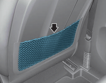
The seatback pocket is provided on the back of the front passenger's seatback.
WARNING
To prevent the Occupant Classification System from malfunctioning:
read more


 Relay Box (Passenger Compartment). Repair procedures