Hyundai Ioniq: Multifunction Switch / Repair procedures
Hyundai Ioniq (AE) 2017-2025 Service Manual / Body Electrical System / Multifunction Switch / Repair procedures
| Removal |
| 1. | Disconnect the negative (-) battery terminal. |
| 2. | Remove the steering wheel. (Refer to Steering System - "Steering Wheel") |
| 3. | Remove the steering column upper and lower shrouds after loosening the screws. (Refer to Body - "Steering Column Shroud Panal") |
| 4. | Remove the clock spring. (Refer to Restraint - "Driver Airbag (DAB) Module and Clock Spring") |
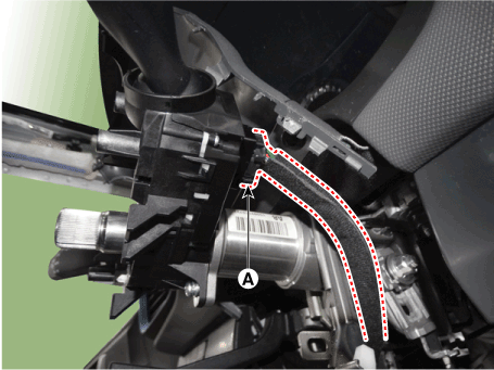
| 5. | Disconnect the multifunction switch connector (A).
|
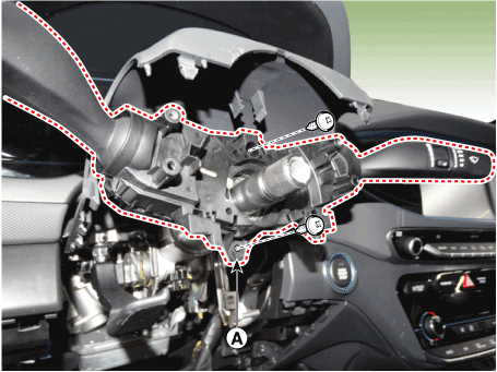
| 6. | Remove the multifunction switch assembly (A) after loosening the screws.
|
| Installation |
| 1. | Install the multifunction switch. |
| 2. | Install the clock spring. |
| 3. | Install the steering column upper and lower shrouds. |
| 4. | Install the steering wheel. |
| 5. | Connect the negative (-) battery terminal. |
| Inspection |
Multifunction Switch Inspection
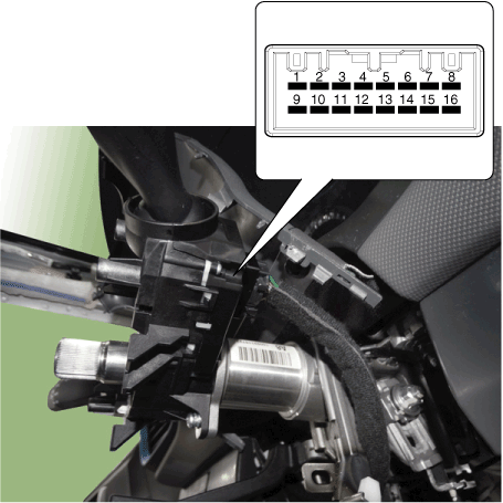
| 1. | Check for continuity between the terminals in each switch position according to the table.
[Left Handle Drive]
[Right Handle Drive]
|
Inspection (with GDS)
| 1. | The body electrocal system can be quickly diagnosed failed parts with vehicle diagnostic system(GDS). The diagnostic system (GDS) provides the following information.
|
| 2. | Select the "Car Model" and the system to be checked in order to check the vehicle with the tester. |
| 3. | Select the "Body Control Module (BCM)" to check the multi function switch. |
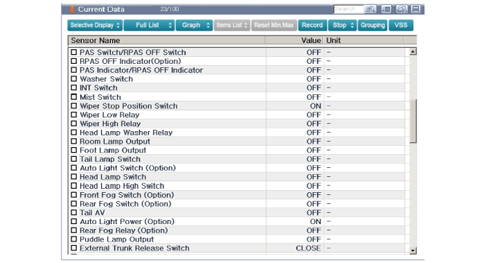
| 4. | Select the "Current Data" menu to search the current state of the input/output data. The input/output data for the sensors corresponding to the multi function switch can be checked.
|

 Horn
Horn
..
Other information:
Hyundai Ioniq (AE) 2017-2025 Service Manual: Components and components location
C..
Hyundai Ioniq (AE) 2017-2025 Service Manual: Description and operation
System OverviewParking Distance Warning (PDW) is an electronic driving aid that warns the driver to be cautious while parking or driving at low speed. The sensor uses ultrasonic waves to detect objects within proximity of the vehicle.PDW consists of four RPS sensors which are detecting the obstacles and transmit the result separated into three warning levels, the first, second and third to BCM by Lin communication...
Categories
- Manuals Home
- 1st Generation Ioniq Owners Manual
- 1st Generation Ioniq Service Manual
- How to Disconnect Normal Charger
- Auto Door Lock/Unlock Features
- High Beam Assist (HBA)
- New on site
- Most important about car
Air Bag Warning Labels
Air bag warning labels, required by the U.S. National Highway Traffic Safety Administration (NHTSA), are attached to alert the driver and passengers of potential risks of the air bag system. Be sure to read all of the information about the air bags that are installed on your vehicle in this Owners Manual.

Copyright © 2025 www.hioniqae.com