Hyundai Ioniq: Cooling System / Water Temperature Control Assembly. Repair procedures
Hyundai Ioniq (AE) 2017-2025 Service Manual / Engine Mechanical System / Cooling System / Water Temperature Control Assembly. Repair procedures
| Removal and installation |
Water Temperature Control Assembly
| 1. | Disconnect the battery negative terminal. |
| 2. | Loosen the drain plug, and drain the engine coolant. Remove the reservoir cap to help drain the coolant faster. (Refer to Cooling System - "Coolant") |
| 3. | Remove the air cleaner assembly. (Refer to Intake and Exhaust System - "Air Cleaner") |
| 4. | Disconnect the radiator upper hose (A).
|
| 5. | Disconnect the heater hoses (A).
|
| 6. | Disconnect the wiring connectors and harness clamps and remove the connector brackets around the water temperature control assembly.
|
| 7. | Disconnect the degassing hose (A) and EGR cooler hose (B).
|
| 8. | Disconnect the oil cooler hose (A).
|
| 9. | Disconnect the water temperature sensor connector (A).
|
| 10. | Remove the water temperature control assembly (A).
|
| 11. | Install in the reverse order of removal. |
Heater Pipe
| 1. | Disconnect the battery negative terminal. |
| 2. | Loosen the drain plug, and drain the engine coolant. Remove the reservoir cap to help drain the coolant faster. (Refer to Cooling System - "Coolant") |
| 3. | Remove the air cleaner assembly. (Refer to Intake and Exhaust System - "Air Cleaner") |
| 4. | Remove the water temperature control assembly. (Refer to Cooling System - "Water Temperature Control Assembly") |
| 5. | Remove the intake manifold. (Refer to Intake and Exhaust System - "Intake Manifold") |
| 6. | Remove the electric EGR control valve cooler pipe (A).
|
| 7. | Remove the heater pipe (A).
|
| 8. | Install in the reverse order of removal. |
| 9. | Fill the radiator with coolant and check for leaks. (Refer to Cooling System - "Coolant") |
| 10. | Start engine and check for leaks. |
| 11. | Recheck the coolant level. |
| Inspection |
| 1. | Remove the outlet fitting, coolant temperature sensor, bracket and gasket from the coolant temperature control assembly. |
| 2. | Submerge the coolant temperature control assembly with the thermostat in the antifreeze and heat the antifreeze slowly.
|
| 3. | Check the valve opening temperature.
If the valve opening temperature is not as specified, replace the thermostat. |
| 4. | Check the valve lift.
If the valve lift is not as specified, replace the thermostat. |
 Water Temperature Control Assembly. Components and components location
Components1. Water temperature control (WTC) outlet fitting2. Water temperature control (WTC) housing3. Water temperature control (WTC) gasket4. Water temperature control (WTC) outlet fitting gasket5...
Other information:
Hyundai Ioniq (AE) 2017-2025 Service Manual: Rear Corner Radar Unit. Repair procedures
Removal1.Disconnect the negative (-) battery terminal.2.Remove the rear bumper.(Refer to Body - "Rear Bumper")3.Remove the rear corner radar unit (A) after loosening the mounting nuts. • Take care not to separate the bracket from rear bumper when removing the rear corner radar sensor...
Hyundai Ioniq (AE) 2017-2025 Service Manual: Electric Parking Brake (EPB). Components and components location
C..
Categories
- Manuals Home
- 1st Generation Ioniq Owners Manual
- 1st Generation Ioniq Service Manual
- Check brakes/Check regenerative brakes, Check Virtual Engine Sound System
- Tilt Steering / Telescope Steering
- If the 12 Volt Battery is Discharged (Hybrid Vehicle)
- New on site
- Most important about car
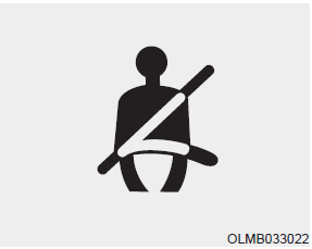
Seat Belt Warning Light
Seat belt warning light

As a reminder to the driver, the seat belt warning light will illuminate and warning chime will sound for approximately 6 seconds each time you place the Engine Start/Stop button to the ON position if the seat belt is unfastened.
Copyright © 2025 www.hioniqae.com


