Hyundai Ioniq: Forward Collision-Avoidance Assist (FCA) system / FCA Warning Message and System Control
The FCA produces warning messages and warning alarms in accordance with the collision risk levels, such as abrupt stopping of the vehicle in front, insufficient braking distance, or pedestrian detection. Also, it controls the brakes in accordance with the collision risk levels.
The driver can select the initial warning activation time in the User Settings in the LCD display. The options for the initial Forward Collision Warning include Early, Normal or Late initial warning time.
Collision Warning (1st warning) - Yellow

This initial warning message appears on the LCD display with a warning chime.
Collision Warning (2nd warning) - Red

This warning message appears on the LCD display with a warning chime. Additionally, some vehicle system intervention occurs by the engine management system to help decelerate the vehicle.
- Your vehicle speed may decelerate moderately.
- The FCA system limitedly controls the brakes to preemptively mitigate impact in
a collision.
Emergency braking (3rd warning)

This warning message appears on the LCD display with a warning chime.
Additionally, some vehicle system intervention occurs by the engine management system to help decelerate the vehicle.
- The FCA system limitedly controls the brakes to preemptively mitigate impact in a collision. The brake control is maximized just before a collision.
Brake operation
- In an urgent situation, the braking system enters into the ready status for prompt reaction against the driver's depressing the brake pedal.
- The FCA provides additional braking power for optimum braking performance, when the driver depresses the brake pedal.
- The braking control is automatically deactivated, when the driver sharply depresses the accelerator pedal, or when the driver abruptly operates the steering wheel.
- The FCA brake control is automatically canceled, when risk factors disappear.
CAUTION
The driver should always use extreme caution while operating the vehicle, whether or not there is a warning message or alarm from the FCA system.
WARNING
The braking control cannot completely stop the vehicle nor avoid all collisions. The driver should hold the responsibility to safely drive and control the vehicle.
WARNING
The FCA system logic operates within certain parameters, such as the distance from the vehicle or pedestrian ahead, the speed of the vehicle ahead, and the driver's vehicle speed. Certain conditions such as inclement weather and road conditions may affect the operation of the FCA system.
WARNING
Never deliberately drive dangerously to activate the system.
 System Setting and Activation
System setting
The driver can activate the FCA by placing the Engine Start/Stop button to the
ON position and by selecting: 'User Settings → Driver Assistance → Forward Collision-Avoidance
Assist'
The FCA deactivates, when the driver deselects the system setting...
 FCA Sensor
In order for the FCA system to operate properly, always make sure the radar sensor
cover is clean and free of dirt, snow, and debris. Dirt, snow, or foreign substances
on the lens may adversely affect the sensing performance of the sensor...
Other information:
Hyundai Ioniq (AE) 2017-2025 Owner's Manual: Reverse Parking Aid Function
When you move the shift lever to the R (Reverse) position, the side view mirror(s) will rotate downwards to aid with driving in reverse. The position of the side view mirror switch (1) determines whether or not the mirrors will move: Left/Right : When either the L (Left) or R (Right) switch is selected, both side view mirrors will move...
Hyundai Ioniq (AE) 2017-2025 Service Manual: Door Scuff Trim. Repair procedures
Replacement[Front door scuff trim] • Put on gloves to prevent hand injuries. • When removing with a flat-tip screwdriver or remover, wrap protective tape around the tools to prevent damage to components...
Categories
- Manuals Home
- 1st Generation Ioniq Owners Manual
- 1st Generation Ioniq Service Manual
- Tilt Steering / Telescope Steering
- Washer Fluid
- How to Disconnect Normal Charger
- New on site
- Most important about car
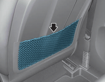
Seatback pocket

The seatback pocket is provided on the back of the front passenger's seatback.
WARNING
To prevent the Occupant Classification System from malfunctioning:
