Hyundai Ioniq: Driveshaft Assembly / Front Driveshaft. Repair procedures
Hyundai Ioniq (AE) 2017-2025 Service Manual / Driveshaft and axle / Driveshaft Assembly / Front Driveshaft. Repair procedures
| Removal |
| 1. | Loosen the wheel nuts slightly. Raise the vehicle, and make sure it is securely supported. |
| 2. | Remove the front wheel and tire (A) from the front hub.
|


| 3. | Loosen the driveshaft caulking nut (A).
|


| 4. | Remove the tie rod end ball joint.
|


| 5. | Loosen the lower arm nut and then remove the lower arm ball joint by using SST(09568-1S100).
|


| 6. | Using a plastic hammer (A), remove the front driveshaft (B) from the knuckle assembly (C).
|

| 7. | Loosen the inner shaft mounting bolts and then remove the driveshaft RH.
|

| 8. | Insert a pry bar between the transaxle case and joint case, and separate the driveshaft.
|

| 9. | Install in the reverse order of removal. |
| 10. | Check the front alignment. (Refer to Suspension System - "Front Alignment") |


Other information:
Hyundai Ioniq (AE) 2017-2025 Service Manual: Auto Defoging Actuator. Description and operation
DescriptionThe auto defogging sensor is installed on front window glass. The sensor judges and sends signal if moisture occurs to blow out wind for defogging. The air conditioner control module receives a signal from the sensor and restrains moisture and eliminates defog by the intake actuator, A/C, auto defogging actuator, blower motor rpm and mode actuator...
Hyundai Ioniq (AE) 2017-2025 Service Manual: Repair procedures
On-vehicle InspectionSpark test1.Check for DTCs. • If a DTC is present, perform troubleshooting in accordance with the procedure for that DTC. (Refer to DTC guide)2.Check if sparks occur.(1)Remove the engine cover...
Categories
- Manuals Home
- 1st Generation Ioniq Owners Manual
- 1st Generation Ioniq Service Manual
- Washer Fluid
- Theft-alarm System
- Checking the Coolant Level
- New on site
- Most important about car
Hybrid Vehicle Engine Compartment
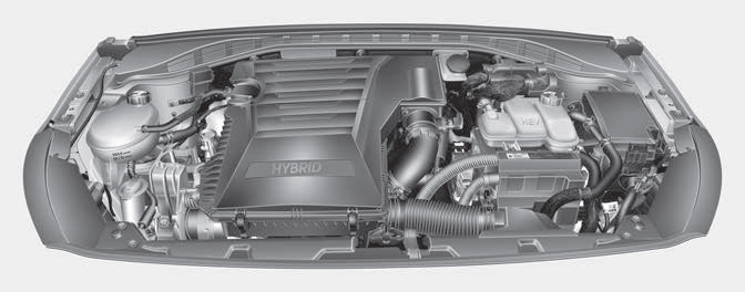
1. Engine oil filler cap
2. Engine oil dipstick
3. Engine coolant cap
4. Engine coolant reservoir
5. Inverter coolant reservoir

Copyright © 2025 www.hioniqae.com