Hyundai Ioniq: Dual Clutch Transmission Control System / Gear Actuator Assembly
Hyundai Ioniq (AE) 2017-2025 Service Manual / DCT(Dual Clutch Transmission) System / Dual Clutch Transmission Control System / Gear Actuator Assembly
- Components and components location
- Specifications
- Description and operation
- Schematic diagrams
- Repair procedures
 Repair procedures
Removal1.Turn ignition switch OFF and disconnect the battery negative (-) terminal.2.Remove the engine room under cover.(Refer to Engine Mechanical System - "Engine Room Under Cover")3...

Other information:
Hyundai Ioniq (AE) 2017-2025 Service Manual: High voltage shut-off procedures
High Voltage Shut-off Procedures • Be sure to read and follow the "General Safety Information and Caution" before doing any work related with the high voltage system. Failure to follow the safety instructions may result in serious electrical injuries...
Hyundai Ioniq (AE) 2017-2025 Service Manual: Components and components location
C..
Categories
- Manuals Home
- 1st Generation Ioniq Owners Manual
- 1st Generation Ioniq Service Manual
- How to Disconnect Normal Charger
- Towing
- Jump Starting
- New on site
- Most important about car
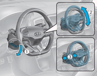
Tilt Steering / Telescope Steering
Adjust the steering wheel so it points toward your chest, not toward your face. Make sure you can see the instrument cluster warning lights and gauges. After adjusting, push the steering wheel both up and down to be certain it is locked in position. Always adjust the position of the steering wheel before driving.
WARNING
NEVER adjust the steering wheel while driving. This may cause loss of vehicle control resulting in an accident.

Copyright © 2025 www.hioniqae.com