Hyundai Ioniq (AE): Engine Control System / Heated Oxygen Sensor (HO2S). Schematic diagrams
| Circuit Diagram |
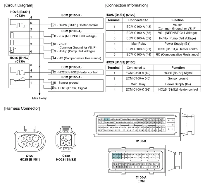
SpecificationHO2S [Bank 1 / Sensor 1] Item Specification Heater Resistance (Ω)2.4 - 4.0 [20°C (68°F)]HO2S [Bank 1 / Sensor 2] (Binary Type) A/F Ratio (λ) Output Voltage (V) RICH0.
Inspection1.Turn the ignition switch OFF.2.Disconnect the HO2S connector.3.Measure resistance between the HO2S terminals 2 and 5 [B1/S1].4.Measure resistance between the HO2S terminals 3 and 4 [B1/S2].
Other information:
Hyundai Ioniq (AE) 2017-2022 Service & Repair Manual: In-car Sensor. Description and operation
DescriptionThe In-car air temperature sensor is built in the heater & A/C control unit.The sensor contains a thermistor which measures the temperature of the inside. The signal decided by the resistance value which changes in accordance with perceived inside temperature, is delivered to heater control unit and according to this signal the contr
Hyundai Ioniq (AE) 2017-2022 Service & Repair Manual: Ambient Temperature Sensor. Components and components location
C
Categories
- Manuals Home
- Hyundai Ioniq Owners Manual
- Hyundai Ioniq Service Manual
- Theft-alarm System
- Checking the Coolant Level
- Engine Clutch System
- New on site
- Most important about car
