Hyundai Ioniq: Indicators And Gauges / Instrument Cluster. Repair procedures
Hyundai Ioniq (AE) 2017-2025 Service Manual / Body Electrical System / Indicators And Gauges / Instrument Cluster. Repair procedures
| Removal |
|
| 1. | Disconnect the negative (-) battery terminal. |
| 2. | Remove the cluster fascia panel. (Refer to Body - "Cluster Fascia Panel") |
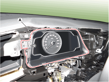
| 3. | Separate the instrument cluster (A) after loosening the mounting screws.
|
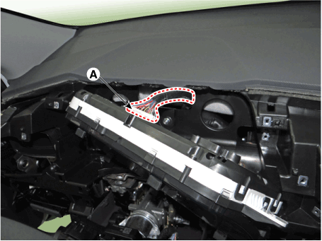
| 4. | Remove the instrument cluster after disconnect the cluster connecotr (A).
|
| Installation |
| 1. | Install the cluster after connect the cluster connectors. |
| 2. | Install the cluster fascia panel. |
| 3. | Connect the negative (-) battery terminal.
|
| Inspection |
| 1. | Check point (Warning indicator)
|
| 2. | Check point (Gauge)
|
Diagnosis with GDS
| 1. | The body electrocal system can be quickly diagnosed failed parts with vehicle diagnostic system (GDS). The diagnostic system (GDS) provides the following information.
|
| 2. | Select the "Car Model" and the system to be checked in order to check the vehicle with the tester. |
| 3. | Select the "Body Control Module (BCM)" to check the "Cluster Module (CLU)". |
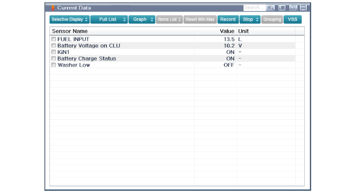
| 4. | Select the "Current Data" menu to search the current state of the input/output data. The input/output data for the sensors corresponding to the cluster module (CLU) can be checked.
|
| 5. | To check the input value of cluster illumination, select option "Actuation Test".
|
CLU Variant Coding
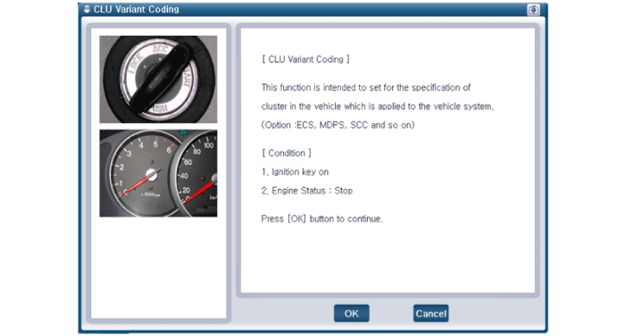
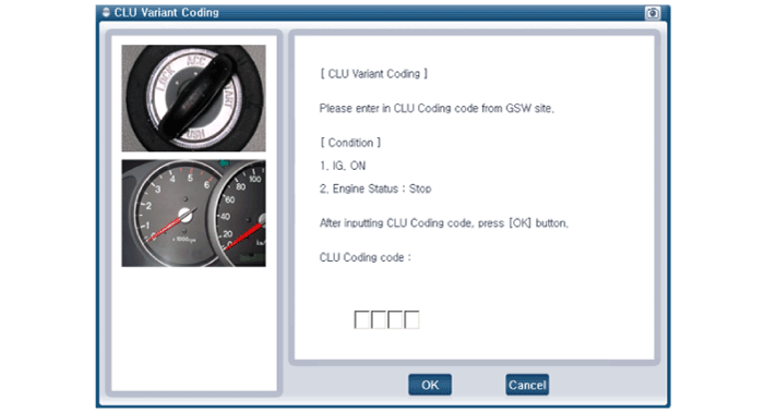
After replacing the cluster with a new one, must be performed the "Variant Coding" procedure.
| 1. | Connect the cable of GDS to the data link connector in driver side crash pad lower panel, turn the power on GDS. |
| 2. | Select model and "BCM". |
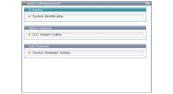
| 3. | Select Variant coding mode to perform.
|
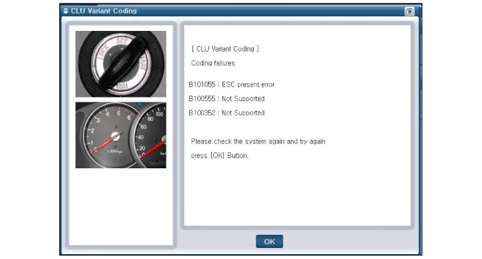
| 4. | If the trouble codes occurred when performing variant coding, try the CLU variant coding again after checking the installation status of CLU system.
|
Other information:
Hyundai Ioniq (AE) 2017-2025 Service Manual: Exhaust Gas Temperature Sensor (EGTS). Repair procedures
Inspection1.Turn ignition switch OFF.2.Disconnect the connector of exhaust gas temperature sensors #1/#2.3.Measure resistance between sensor signal terminal and ground terminal.4.Check that the resistance is within the specification.Exhaust Gas Temperature Sensor [EGTS #1, #2 (T3, T4)] Temperature [°C (°F)] Resistance (kΩ) -40 (-40)0...
Hyundai Ioniq (AE) 2017-2025 Service Manual: Specifications
S..
Categories
- Manuals Home
- 1st Generation Ioniq Owners Manual
- 1st Generation Ioniq Service Manual
- Check Hybrid system, Check Hybrid system. Turn engine Off
- Check brakes/Check regenerative brakes, Check Virtual Engine Sound System
- If the 12 Volt Battery is Discharged (Hybrid Vehicle)
- New on site
- Most important about car
Rear Seats
Folding the rear seat
The rear seatbacks can be folded to facilitate carrying long items or to increase the luggage capacity of the vehicle.
WARNING
Never allow passengers to sit on top of the folded down seatback while the vehicle is moving. This is not a proper seating position and no seat belts are available for use. This could result in serious injury or death in case of an accident or sudden stop. Objects carried on the folded down seatback should not extend higher than the top of the front seatbacks. This could allow cargo to slide forward and cause injury or damage during sudden stops.
Copyright © 2025 www.hioniqae.com


