Hyundai Ioniq: Electric A/C Compressor / Repair procedures
[Electric A/C Compressor body inside inspection]
| 1. | Electric compressor body inside check procedure. | 1) | Remove the low-pressure pipe from the electric compressor. |
| 2) | Check if the copper wire and white thread inside of the compressor was contaminated. 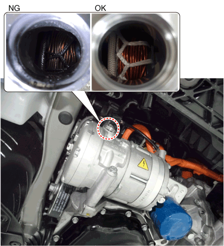
|
|
| 2. | To check the compressor motor, measure the resistance of the 3-phase power pin. | 1) | If the 3-phase resistance value is out of specification, it means motor malfunction. Replace the whole compressor assembly. 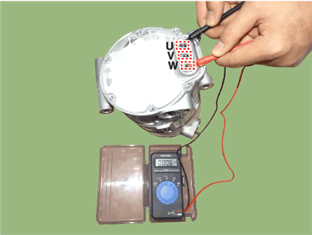
|
|
[Electric A/C Compressor inverter inspection]
| 1. | To check the compressor inverter, measure the resistance value of the compressor's high voltage pin, low voltage pin and insulation. | (1) | High voltage pin Normal resistance value : 100 Ω↑ Abnormal resistance : 100 Ω↓ |
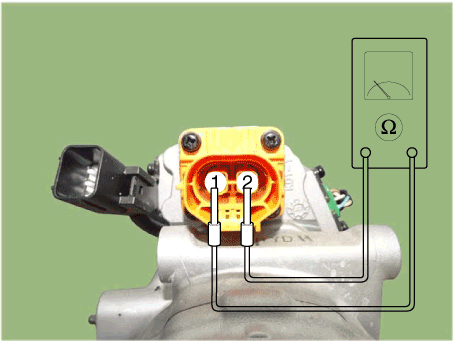
|
| (2) | Low voatage pin | a. | Measure CAN HIGH/LOW Resistance - Measure terminals 2 and 5. Normal : 120 Ω Abnormal : inverter short-circuited (≒0Ω) |
|
| b. | Measure CAN Ground Resistance - Measure terminals 1 and 2 / 1 and 5. Normal : 13~14 KΩ / 200~600 KΩ (High Performance DSP Specifications) Abnormal : inverter short-circuited (≒0Ω) |
|
| c. | Measure Interlock HIGH/LOW Resistance measure (Connect high voltage connector (A) and measure low voltage (B) 3 and 6 resistance.) Normal : Below 1.0 Ω Abnormal : MΩ |
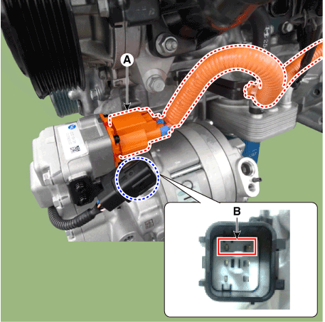
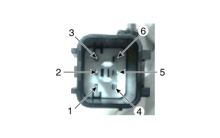
Pin NO
| Function
| Pin NO
| Function
| 1
| GND 12V
| 4
| IG 12V
| 2
| CAN LOW
| 5
| CAN HIGH
| 3
| Interlock (-)
| 6
| Interlock (+)
|
|
|
|
|
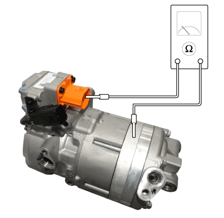
| 2. | Compressor insulation resistance measurement. Normal resistance value : check insulation resistance (Minimum : 100 MΩ) (@500 Vdc, no coolant) |
|
| 1. | If the compressor is marginally operable, run the engine at idle speed, and let the air conditioning work for a few minutes, then shut the engine off. |
| 2. | Cut off the high voltage. (Refer to Generals - "High Voltage Cut-off Procedure") |
| 3. | Recover the refrigerant with a recovery / charging station. | •
| Use dedicated recovery/charge station for filling R134a or R1234y and POE. If the POE is mixed with PAG oil, the compressor may defective or safety related accident may occur due to decreased volumetric resistivity. |
|
|
| 4. | Remove the engine room under cover. (Refer to Engine Mechanical System - "Engine Room Cover") |
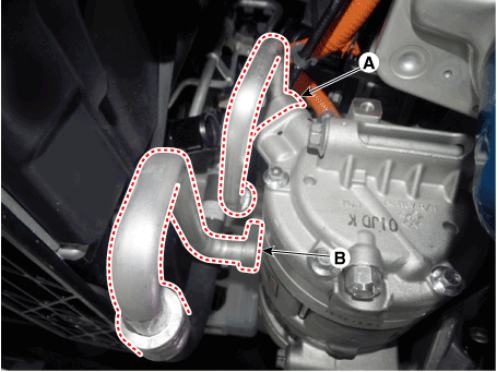
| 5. | Remove the bolts, then disconnect the suction line (A) and discharge line (B) from the compressor. Tightening torque : 7.8 - 11.8 N.m (0.8 - 1.2 kgf.m, 5.8 - 8.7 Ib-ft) |
| •
| To protect the system from moisture and dust contamination, plug it in or cap it immediately after disconecting it. |
|
|
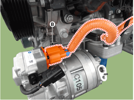
| 6. | Disconnect the high voltage connector (A) and electric compressor connector (B) 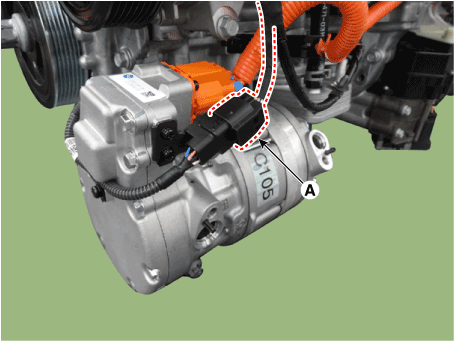
|
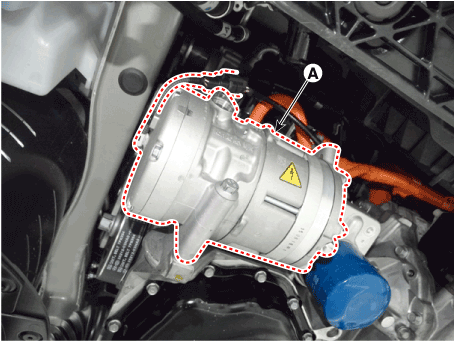
| 7. | Remove the compressor (A) by loosening the mounting bolts. Tightening torque : 20.0 - 32.95 N.m (2.04 - 3.36 kgf.m, 14.75 - 24.30 Ib-ft) |
|
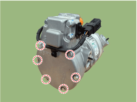
| 8. | Remove the bolts from the inverter. | •
| Do not re-use the inverter fastening bolt. |
| •
| Never remove unmarked bolts. |
|
|
| 9. | Remove the inverter (A) and compressor body (B). 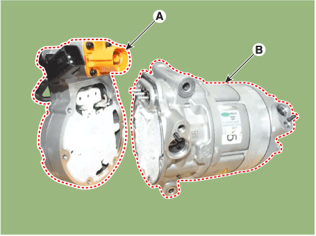
| •
| When removing the inverter, be careful not to damage, twist or bend the 3-phase power pin (B). |
| •
| To prevent the inverter from getting contaminated, remove dust or dirt from the exterior of the compressor. |
| •
| In order to prevent the inverter from getting contaminated, do not open the package until the inverter is completely installed. 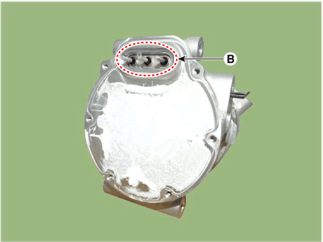
|
|
|
| •
| If you install a new compressor, drain all the refrigerant oil from the removed compressor and measure its volume. Subtract the volume of drained oil from the original capacity. The result is the amount of oilcompressor oil you should drain from the new compressor (through the suction fitting). |
| •
| Replace the O-rings with new ones at each fitting, and apply a thin coat of refrigerant oil before installing them. Be sure to use the right O-rings for R-134a or 1234yf to avoid leakage. |
| •
| To avoid contamination, do not return the oil to the container once dispensed, and never mix it with other refrigerant oils. |
| •
| Immediately after using the oil, replace the cap on the container and seal it to avoid moisture absorption. |
|
| •
| Use dedicated recovery/charge station for filling R134a or R1234y and POE. If the POE is mixed with PAG oil, the compressor may defective or safety related accident may occur due to decreased volumetric resistivity. |
|
| 1. | Replace the problematic part of the motorized compressor body and inverter, and reuse the remaining parts. |
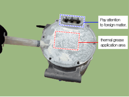
| 2. | Apply the thermal grease as in the following before replacing the inverter. | •
| When replacing the inverter, be careful for static electricity and maintain a clean room (keep constant temperature and humidity : 22°C [71.6°F] - 23°C [73.4°F], 50%) |
| •
| Make sure to use the provided thermal grease as generic grease is not allowed. |
| •
| Remove the foreign material by using alchohol when applying thermal grease. |
| •
| Do not open the package until the inverter is installed, to prevent the inverter from getting contaminated. |
|
|
| 3. | Install the inverter gasket (A). 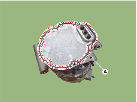
|
| 4. | Install the inverter (A) and compressor body (B) while being careful not to damage the 3-phase power pin. | •
| When installing the inverter, be careful not to damage, twist or bend the 3-phase power pin. |
| •
| Do not re-use the inverter fastening bolt and gasket. |
|

|
| 5. | Assemble the inverter with new fastening bolts. Tightening torque : 5.9 - 6.9 N·m (0.6 - 0.7 kgf·m, 4.3 - 5.1 Ib·ft) |
| •
| Excessive or insufficient torque may cause of PCB inside the inverter bending by engine vibration at inverter assemble. |
| •
| Do not re-use the inverter fastening bolts. |
|

|
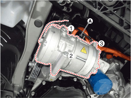
| 6. | Make sure the compressor mounting bolt with the correct length is screwed in. Tighten the mounting bolts with the specified tightening order. Tightening torque : 20.0 - 32.95 N.m (2.04 - 3.36 kgf.m, 14.75 - 24.30 Ib-ft) |
|
| 7. | Install the compressor connector (A) and high voltage connector (B). 

|
| 8. | Install the bolts, then disconnect the suction line (A) and discharge line (B) from the compressor. Tightening torque : 7.8 - 11.8 N.m (0.8 - 1.2 kgf.m, 5.8 - 8.7 Ib-ft) |

|
| 9. | Install the engine room under cover. (Refer to Engine Mechanical System - "Engine Room Cover") |
Other information:
Description•
Various devices containing semiconductor are used in HPCU.And heat is generated when the HPCU operates.•
These devices are connected to the high voltage directly and cause heat hotter than the electrical devices of an internal combustion engine...
■ Front
■ Rear
If towing is necessary, we recommend you to have it done by an authorized HYUNDAI
dealer or a commercial tow truck service.
If a towing service is not available in an emergency, your vehicle may be temporarily
towed using a cable or chain secured to the emergency towing hook at the rear of
the vehicle...
Categories
Seat belt warning light

As a reminder to the driver, the seat belt warning light will illuminate and
warning chime will sound for approximately 6 seconds each time you place the Engine
Start/Stop button to the ON position if the seat belt is unfastened.
read more
 Troubleshooting


