Hyundai Ioniq: Tires/Wheels / Alignment. Repair procedures
Hyundai Ioniq (AE) 2017-2025 Service Manual / Suspension System / Tires/Wheels / Alignment. Repair procedures
| Adjustment |
| Front Wheel Alignment |
|
Toe
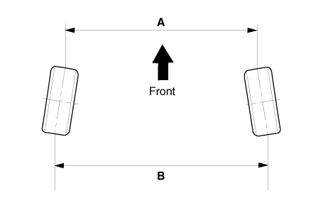
B - A > 0 : Toe in B - A < 0 : Toe out |
Toe Adjustment
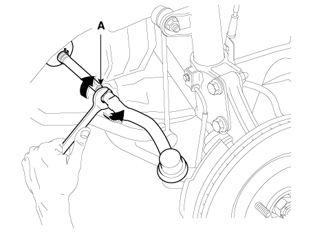
| 1. | Loosen the tie rod end lock nut. |
| 2. | Remove the bellows clip to prevent the bellows from being twisted. |
| 3. | Adjust the toe by screwing or unscrewing the tie rod. Toe adjustment should be made by turning the right and left tie rods by the same amount.
|
| 4. | When completing the toe adjustment, install the bellows clip and tighten the tie rod end lock nut to specified torque.
|
Camber
Camber angle : Australia : -0.5° ± 0.5° General/M.E/China : -0.38° ± 0.5° |
When the wheel tilts out at the top, then the camber is positive (+).
When the wheel tilts in at the top, then the camber is negative (-).
Camber and Caster are pre-set at the factory, so they do not need to be adjusted. If the camber and caster are not within the standard value, replace or repair the damaged parts and then inspect again.

| ITEM | Description |
| A | Positive camber angle |
| B | True vertical |
| C | Strut centerline |
Caster
Caster is the tilting of the strut axis either forward or backward from vertical. A backward tilt is positive (+) and a forward tilt is negative (-).
Caster is pre-set at the factory and doesn't need to be adjusted. If the caster is not within the standard value, replace the bent or damaged parts.
Caster : 4.5° ± 0.5° |
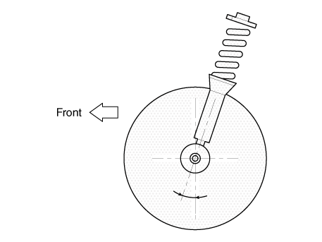
King-pin angle
King-pin angle : 14.0°±0.5° |

|
| Rear Wheel Alignment |
|
Toe

B - A > 0 : Toe in B - A < 0 : Toe out |
Toe Adjustment
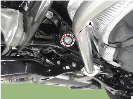
| 1. | Loosen the nut holding the assist arm cam bolt (A). |
| 2. | Adjust rear toe by turning the rear assist arm cam bolt (A) clockwise or counter clockwise. Toe adjustment should be made by turning the right and left cam bolt by the same amount.
|
| 3. | When completing the toe adjustment, tighten the nut to specified torque.
|
Camber Adjustment
| 1. | Loosen the nut holding the rear lower arm cam bolt (A). |
| 2. | Adjust rear camber by turning the rear lower arm cam bolt (A) clockwise or counter clockwise. Rear camber adjustment should be made by turning the right and left cam bolt by the same amount.
|
 Wheel. Repair procedures
Hub nut tightening sequenceTighten the hub nuts as follows. Tightening torque : 107.9 - 127.5 N.m (11.0 - 13.0 kgf.m, 79.6 - 94.0 lb-ft)
•
When using an impact gun, final tightening torque should be checked using a torque wrench...
Other information:
Hyundai Ioniq (AE) 2017-2025 Owner's Manual: Check Tire Inflation Pressure
Check your tires, including the spare tire, once a month or more. How to check Use a good quality tire pressure gauge to check tire pressure. You can not tell if your tires are properly inflated simply by looking at them. Radial tires may look properly inflated when they are under-inflated...
Hyundai Ioniq (AE) 2017-2025 Service Manual: Description and operation
DescriptionIn a hybrid electric vehicle, HCU (an upper level controller), LDC (power converter), and inverter are integrated in the HPCU. HPCU is located on the left side of the engine compartment.The inverter provides high-voltage AC current to the two motors (drive motor and HSG) and controls them optimally based on the driving conditions through communication with the HCU...
Categories
- Manuals Home
- 1st Generation Ioniq Owners Manual
- 1st Generation Ioniq Service Manual
- If the 12 Volt Battery is Discharged (Hybrid Vehicle)
- Tilt Steering / Telescope Steering
- Child-Protector Rear Door Locks
- New on site
- Most important about car
Driver Position Memory System
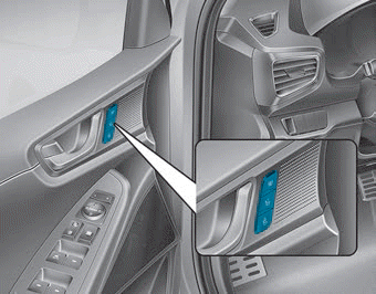
The Driver Position Memory System is provided to store and recall the following memory settings with a simple button operation.
- Driver's seat position
- Side view mirror position
- Instrument panel illumination intensity
Copyright © 2025 www.hioniqae.com


