
Hyundai Ioniq (AE): Air Conditioning System / Components and components location
| Component Location Index |
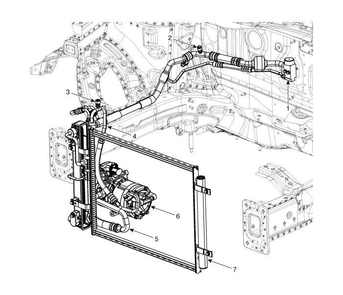
| 1. Expansion valve 2. Service port (Low pressure) 3. Service port (High pressure) 4. Discharge hose | 5. Suction & Liquid tube assembly 6. Electric A/C compressor 7. Condenser |
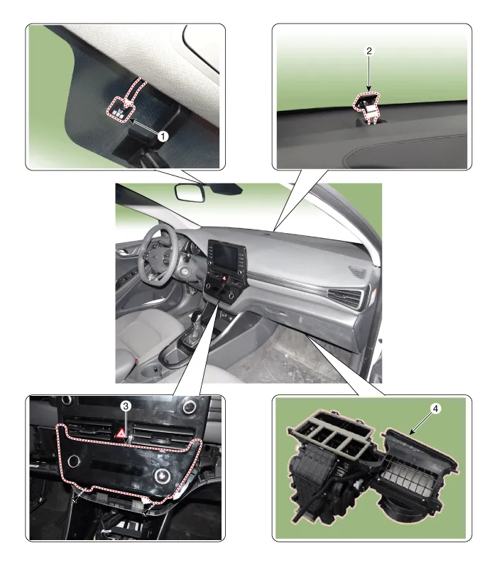
| 1. Auto defogging sensor 2. Photo sensor | 3. Heater & A/C control unit 4. Heater & Blower unit |
Refrigerant System Service BasicsRefrigerant Identification• Do not mix HFO-1234yf (R-1234yf) in the vehicle with other refrigerant, such as R-12, R-134a and etc.
Oil Specification1.The HFC-134a system requires synthetic (POE) compressor oil whereas the R-12 system requires mineral compressor oil. The two oils must never be mixed.
Other information:
Hyundai Ioniq (AE) 2017-2022 Service & Repair Manual: Auto Defogging Sensor. Description and operation
DescriptionThe auto defogging sensor is installed on the front window glass. The sensor judges and sends signal if moisture occurs to blow out wind for defogging. The air conditioner control module receives signal from the sensor and restrains moisture and eliminate defog by controlling the intake actuator, A/C, auto defogging actuator, blower moto
Hyundai Ioniq (AE) 2017-2022 Service & Repair Manual: Troubleshooting
Trouble Symptom ChartsTrouble Symptom 1Trouble Symptom 2 Trouble symptom Probable cause Remedy The set vehicle speed varies greatly upward or downward"Surging" (repeated alternating acceleration and deceleration) occurs after settingMalfunction of the vehicle speed se
Categories
- Manuals Home
- Hyundai Ioniq Owners Manual
- Hyundai Ioniq Service Manual
- If the 12 Volt Battery is Discharged (Hybrid Vehicle)
- Troubleshooting
- Jump starting procedure
- New on site
- Most important about car
