
Hyundai Ioniq (AE): Front Suspension System / Components and components location
Hyundai Ioniq (AE) 2017-2022 Service & Repair Manual / Suspension System / Front Suspension System / Components and components location
| Components Location |
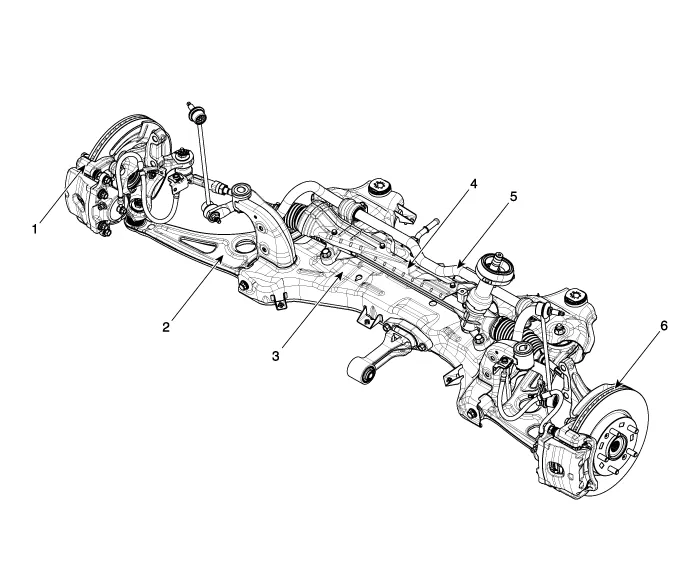
| 1. Brake caliper 2. Lower arm 3. Sub frame | 4. Steering gearbox 5. Stabilizer bar 6. Brake disc |
Components1. Strut assembly2. Lock nut3. Insulator 4. Strut bearing & Spring upper pad5. Bumper rubber6. Dust cover7. Coli spring8. Spring lower pad
Categories
- Manuals Home
- Hyundai Ioniq Owners Manual
- Hyundai Ioniq Service Manual
- Hybrid Vehicle Engine Compartment
- Components and components location
- Jump starting procedure
- New on site
- Most important about car

Copyright В© 2026 www.hioniqae.com - 0.0363